01
Smooth compound curves
Modules bend to the designed radius, so the surface reads as one continuous ribbon.
Creative Display
Flexible modules mounted on a formed frame to create wave, ribbon and curved feature walls.
P2.5–P4
Pixel pitch
3,000 nits
Brightness
>7680Hz
Refresh rate
Wave screens use flexible modules fixed to a CNC-formed frame, producing a smooth compound curve without visible cabinet steps. They are used as feature walls in retail, museums and hotel lobbies where a flat screen would look ordinary.
Every unit is assembled and tested in Shenzhen before packing. Cabinet drawings, pixel map and control-system settings are supplied with the shipment, so the configuration on site matches the quotation.
Specifications
Engineering decisions behind Wave LED Screen, and what they change on site.
Modules bend to the designed radius, so the surface reads as one continuous ribbon.
The frame is cut to the drawing, keeping the curve consistent between production and site.
Pixel mapping is supplied so artwork follows the curve instead of being cropped.
Wave LED Screen
Wave LED Screen is engineered around the site rather than a standard cabinet grid. The structure, module layout and mounting points are produced from a drawing that fixes the shape, viewing direction and access route.
A steel or aluminium frame carries the display and transfers wind and self-weight to the building or foundation. The section is selected from the installation height and site load.
Modules are arranged to the drawing, with cut modules and edge details planned so the visible shape matches the design.
Power supplies and receiving cards sit in a protected enclosure with a service route that does not disturb the visible surface.
Base plate, wall bracket or suspension points are detailed for the actual structure, including access for adjustment after installation.
The decisions that affect how Wave LED Screen looks, installs and stays serviceable on site.
The display is not forced into a rectangular cabinet grid. The outline, radius and edge treatment follow the approved drawing.
Module orientation and brightness are set for the direction people actually approach the installation.
A pixel map is supplied so artwork can be produced for the exact shape without stretching or guessing the active area.
Access panels and removable modules are planned before fabrication, so maintenance does not require dismantling the artwork.
Service is planned before the wall is built. Modules, cards and power supplies are replaced from the access direction agreed on the drawing.
Service panels are located on the least visible face. Modules and electronics are reached without removing the whole installation.
Replacement modules are supplied to the project drawing. The pixel map identifies the exact position for the replacement.
Outdoor and pole-mounted units include a fixing and structure inspection schedule in the handover pack.
Product credibility
Wave LED Screen is built on the same production line as our project walls. Cabinets, modules and control settings are recorded per batch, and the documentation travels with the shipment so the site team is not working from memory.
ISO 9001
Factory process control
CE / RoHS / FCC
Product compliance
Batch tested
Aging and calibration record
2–3 years
Standard warranty
Creative display selection
Creative displays are engineered around a location rather than a catalogue cabinet. The site, viewing direction and movement idea decide whether the project is a light pole, an art surface or a mechanical build.
A street pole, a plaza sculpture and a facade each have different wind, foundation and access conditions. The structure is selected from the actual installation point.
Static art surfaces and light poles use a fixed frame. Mechanical displays add motors, travel and safety controls, which change the structure and maintenance plan.
The pixel map, content ratio and service route are agreed before fabrication. A shape that cannot be serviced or mapped is not a finished design.
Deployment playbook
The same brief can lead to a street pole, a sculptural surface or a moving wall. The site and the content idea decide.
A pole integrates display, power and control at street level. Wind load, foundation and remote publishing are part of the scope.
Light pole · P1.86–P3.846 · 3–12 m
A free-form surface turns a drawing into a lit object. The module layout and pixel map follow the artwork geometry.
Art screen · P1.9–P8 · custom shape
Motorized modules open, rotate or fold in sync with video. Safety limits and factory testing are part of the build.
Mechanical · P1.5–P2.5 · servo motion
Delivery control
Creative work moves from concept to structure drawing, mock-up and factory test. Each stage fixes a decision that cannot be recovered later on site.
Handover pack
Cabinet layout, control points, power distribution and the service direction are fixed before materials are cut. The approved drawing becomes the reference for every later check.
LED modules, driver ICs and power supplies are drawn from the same production batch where the order size allows, then labelled by cabinet position.
Assembled cabinets run through an aging cycle and white-balance calibration. Faults found at this stage are corrected before packing, not after arrival.
Cabinets are packed against the transport method and site access. The handover pack includes the structure drawing, pixel map, content guide and service schedule.
Buyer questions
These are the points that most often change the specification after the first enquiry. If your question is not here, send it with the site details.
Ask an engineerYes. Send the drawing, a sketch or a reference image. We review the geometry, viewing direction, structure and service access before quoting.
The structure and foundation are reviewed against the installation height and local conditions. The display frame is designed with the support structure, not separately.
Yes. A pixel map is supplied for the active area so the content team can build artwork for the exact shape without stretching.
Creative projects are scheduled after drawing approval. The timeline depends on structure, motion and mock-up requirements, and is stated in the project plan.
Next step
Use the application guide and references to test the site, structure and content idea before drawing approval.
See how this series is specified against viewing distance, room light and installation constraints.
Open application guideReview project types, cabinet formats and the delivery scope used on comparable installations.
View case studiesRequest the current specification sheet, cabinet drawing and control compatibility list.
Open downloadsSend the wall size, viewing distance and site photos. We reply with a configuration and quotation.
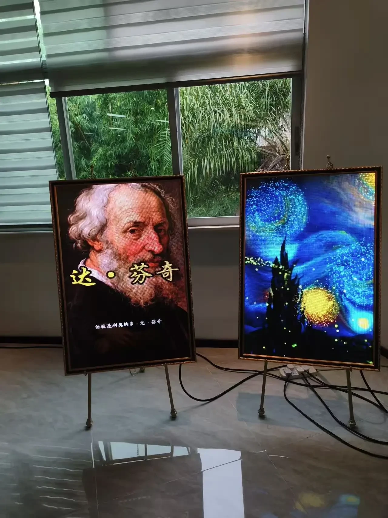
Request a quote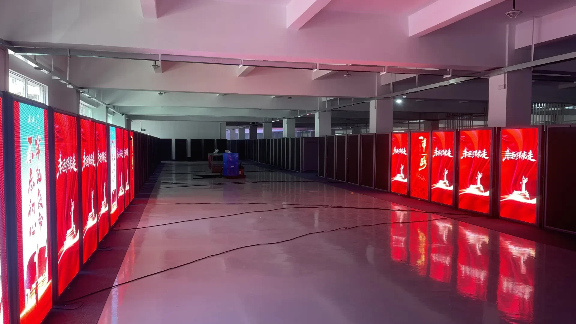
Light Pole LED Screen
P1.86–P3.846 · 5,500 nits
Custom cylindrical cabinet
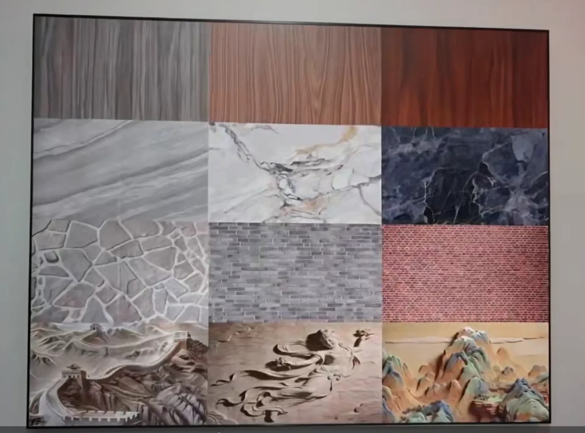
Art Frame LED Screen
P1.5–P2.5 · 600 nits
300 × 300mm framed unit
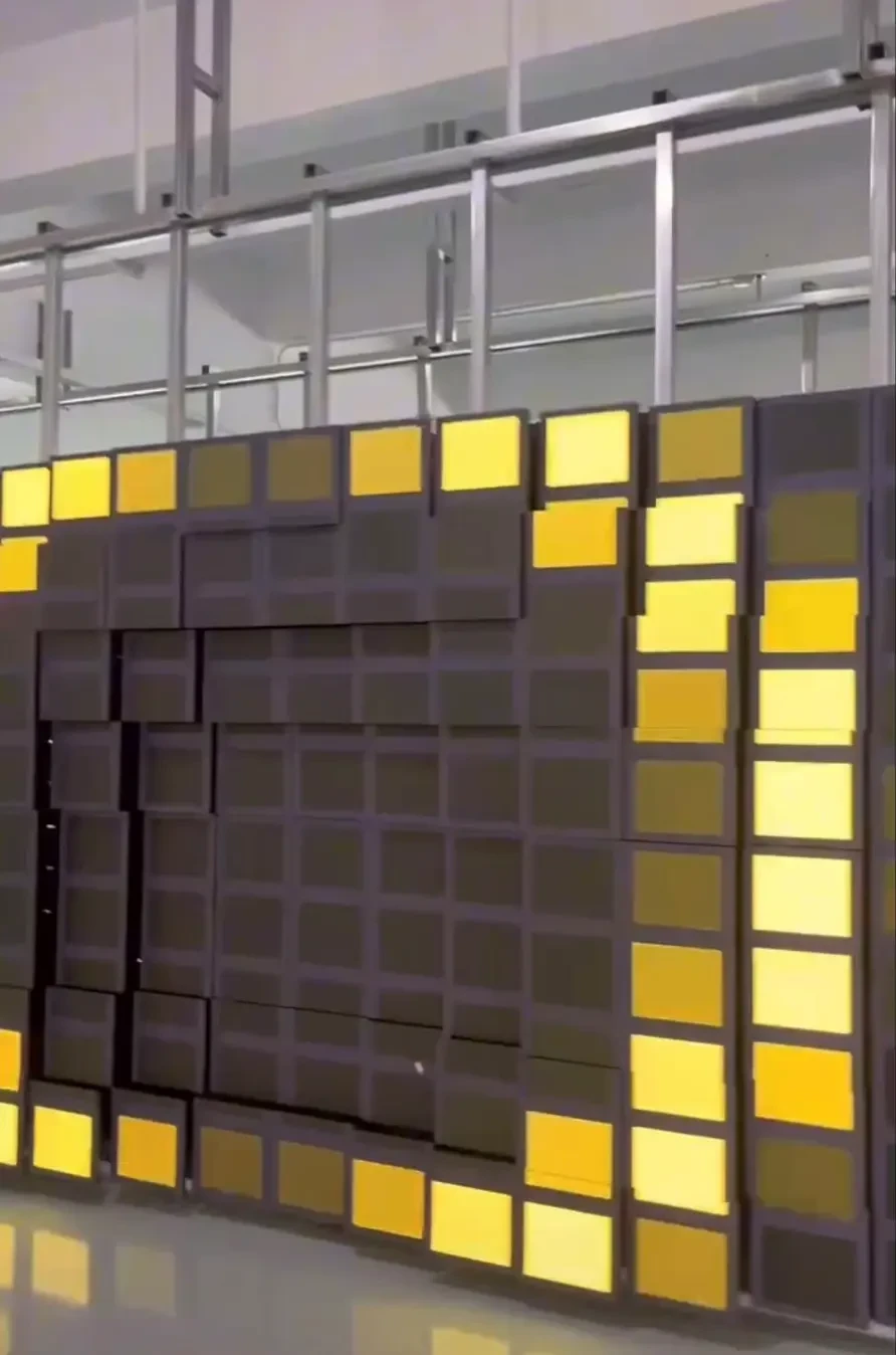
Mechanical LED Screen
P1.5–P2.5 · 5,000 nits
Motorised modular panel
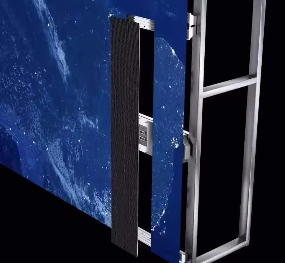
Poster LED Display
P2.5–P3 · 1,000 nits
640 × 1920mm poster frame

Spherical LED P2.5
2.5mm · 1,000 nits
Sphere, 0.5–2m diameter

Spherical LED P3
3mm · 1,200 nits
Sphere, 0.8–3m diameter

Spherical LED P4 Outdoor
4mm · 5,000 nits
Sphere, 1–3m diameter, IP65
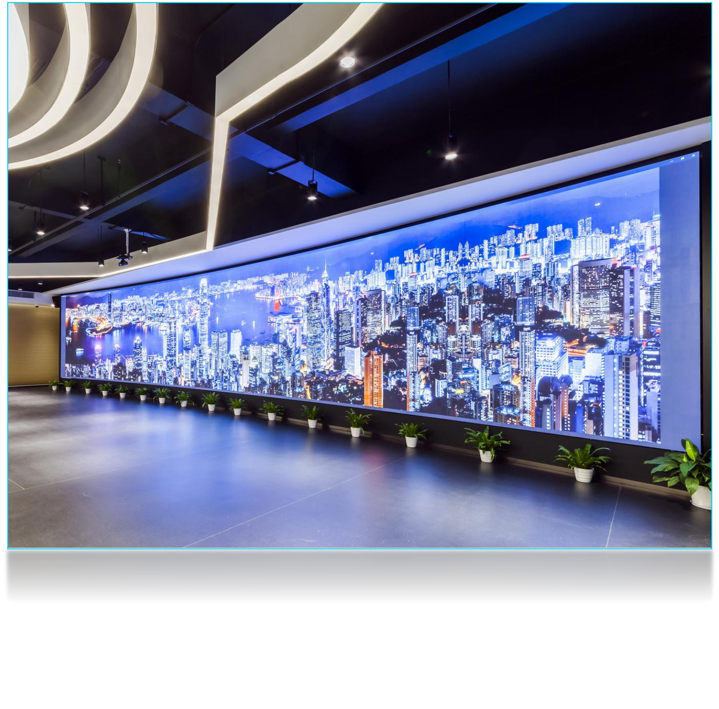
Cylinder LED P2.5
2.5mm · 1,000 nits
Cylinder, 0.5–2m diameter
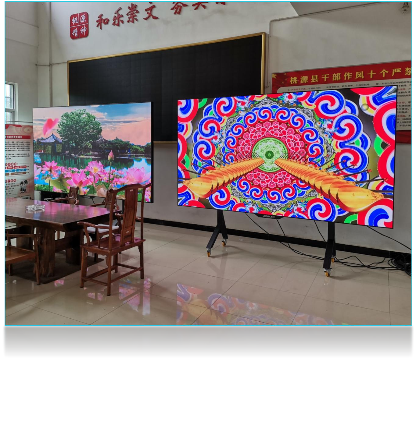
Cylinder LED P3
3mm · 1,200 nits
Cylinder, 0.8–3m diameter

Cylinder LED P4 Outdoor
4mm · 5,000 nits
Cylinder, 1–4m diameter, IP65

Cylinder LED P5 Outdoor
5mm · 5,500 nits
Cylinder, 1–5m diameter, IP65
Send viewing distance, wall size and installation type. We reply with cabinet quantity, control layout and a quotation within 24 business hours.