MIP LED Display · Product Series
MIP brightness in a sealed package.
P0.9 · P1.2 · P1.5 · P1.8
Micro LED in Package places each RGB die in its own package before assembly, combining the brightness headroom of discrete LEDs with the uniform surface of COB. MIP is the practical choice where the wall must stay bright and colour-stable for long operating hours.
Advantages
- 3,850 nits brightness
- 15,000:1 contrast · IP43 front
- >7680Hz · 16-bit grayscale
- Novastar / Colorlight compatible
Models
All models share >7680Hz refresh, 16-bit grayscale and 170° viewing angle.
Advantages
Micro LED in Package
Each RGB die is packaged before the module is assembled.
3,850 nits
Higher brightness headroom for lit control rooms.
Uniform black surface
Low reflectance keeps the wall visually calm when off.
>7680Hz refresh
Stable image for cameras and long recording sessions.
Heat-managed modules
Thermal path designed for 24/7 operation.
Novastar / Colorlight
Compatible with mainstream control systems.
MIP Series Specifications
| Parameter | P0.9 | P1.2 | P1.5 | P1.8 |
|---|---|---|---|---|
| Pixel pitch | 0.9mm | 1.2mm | 1.5mm | 1.8mm |
| Brightness | 3,850 nits | 3,850 nits | 3,850 nits | 3,850 nits |
| Contrast | 15,000:1 | 15,000:1 | 15,000:1 | 15,000:1 |
| Avg power | ≤180 W/m² | ≤200 W/m² | ≤220 W/m² | ≤240 W/m² |
| Cabinet size | 600×337.5mm | 600×337.5mm | 600×337.5mm | 600×337.5mm |
Typical values at 25°C. Cabinet size 600×337.5mm; confirm final configuration on the datasheet.
MIP LED Display
Structure introduction
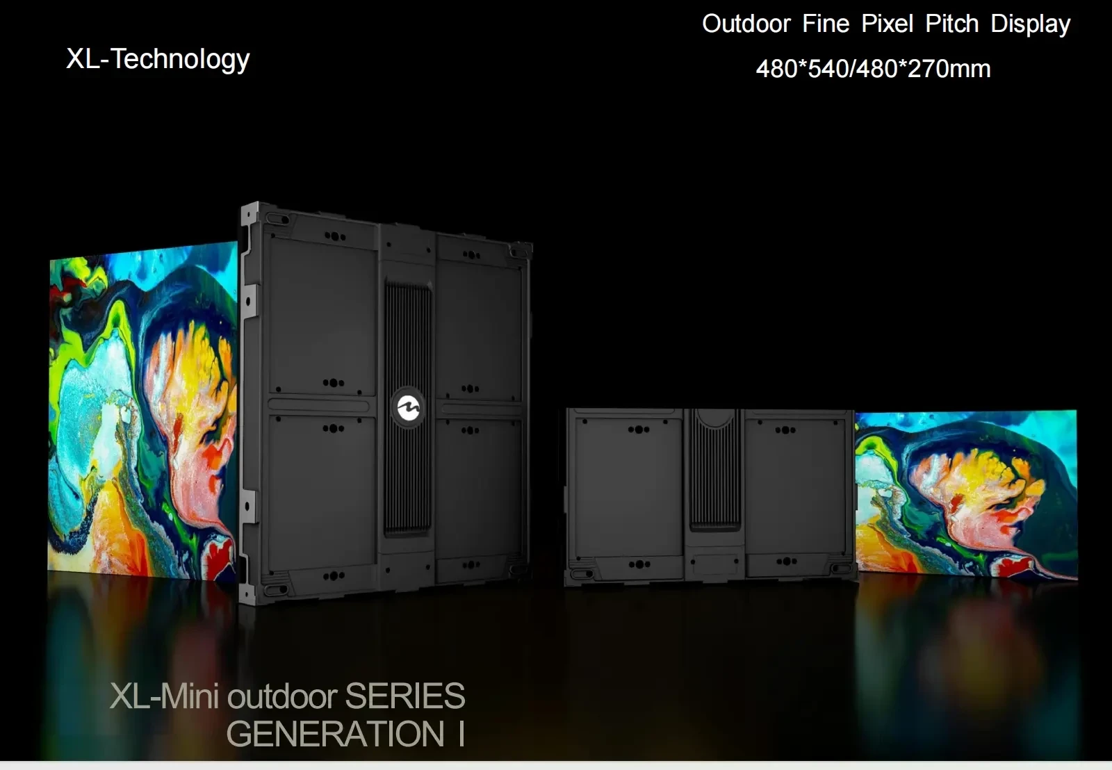
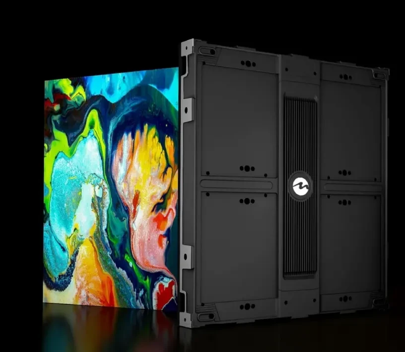
MIP display uses MIP packaging: each RGB die is packaged before the module is assembled. The 600 × 337.5mm cabinet then carries the packaged module, driver and power supply as a front-service unit.
Series specification
01
Packaged LED die
Packaging protects each die before module assembly and creates a more uniform black surface than an exposed lamp array.
02
Module and driver board
The packaged LEDs are mounted to the driver board as one module, keeping the pixel structure stable through handling and service.
03
Cabinet and mounting frame
A machined frame holds the module plane and provides wall or recessed mounting points. The frame is the reference for seam planning.
04
Power and control carrier
Receiving cards and power supplies sit on a serviceable carrier behind the module, accessible from the front.
Design details
The decisions that affect how MIP LED Display looks, installs and stays serviceable on site.
01
Uniform black face
The packaged surface lowers reflectance and keeps the wall visually calm when content is dark, which suits control rooms and boardrooms.
02
Brightness headroom
3,850 nits gives the wall room to run at reduced output in dim rooms while still meeting daylight conditions in lobbies.
03
Thermal path for 24/7 use
The package and board are selected for continuous operation, with heat spread across the cabinet rather than concentrated at the module centre.
04
Camera-safe drive
High refresh and grayscale depth keep scan lines out of video calls and broadcast footage.
Front maintenance
Service is planned before the wall is built. Modules, cards and power supplies are replaced from the access direction agreed on the drawing.
Front module access
The module is released from the front, so a wall in a finished room can be serviced without rear clearance.
Driver and PSU replacement
Receiving cards and power supplies are field-replaceable units. The cabinet can remain on the wall during replacement.
Colour matching
Spare modules are supplied from the project batch and checked against the calibration record before dispatch.
Product credibility
Documented before it ships
MIP LED Display is built on the same production line as our project walls. Cabinets, modules and control settings are recorded per batch, and the documentation travels with the shipment so the site team is not working from memory.
ISO 9001
Factory process control
CE / RoHS / FCC
Product compliance
Batch tested
Aging and calibration record
2–3 years
Standard warranty
Quality record
- CE, RoHS and FCC documentation for the supplied configuration.
- Aging and white-balance calibration record per batch.
- Cabinet drawing, pixel map and control settings in the handover pack.
- Spare modules matched to the original production batch.
Applications
Command centres
Bright, colour-stable walls for continuous monitoring.
Corporate boardrooms
Presentation-grade fine pitch for meeting spaces.
Broadcast studios
Clean background walls for virtual sets.
Security monitoring
Multi-window video walls for surveillance.
Data visualisation
Dense pixel arrays for charts and dashboards.
Museums & exhibitions
High-resolution displays for close viewing.
MIP selection and delivery
Use MIP where brightness headroom matters
MIP packaging gives a uniform black face with useful brightness headroom. It is a strong fit for rooms that mix presentations, camera work and daylight, but it should be selected against COB on contrast, service and budget.
013,850 nits
Check the room light first
If the wall faces windows or is used with house lights up, MIP's brightness range gives more room to run at reduced output without losing colour. In a dark room, COB's contrast may be the stronger criterion.
02P0.9–P1.8
Set the pitch from the table
P0.9 suits command centres and close executive viewing; P1.2–P1.5 is the usual boardroom and studio range; P1.8 fits larger rooms where the nearest viewer is beyond 6 m.
03Front-service cartridge
Plan thermal and service access
MIP walls often run all day. Confirm the cabinet thermal path, the front-service route and the spare-module plan before the wall is closed in.
Deployment playbook
Where MIP is the practical choice
MIP is specified when the image must stay stable across mixed lighting and the wall has to remain serviceable in a finished room.
01
Command centres
Multiple operators view the wall from different angles for long shifts. Uniform black, high refresh and a controlled thermal path keep the surface readable without glare.
P0.9–P1.2 · 3,850 nits · 24/7 plan
02
Broadcast and studio walls
Camera exposure changes quickly. High refresh and grayscale depth suppress scan lines, while brightness headroom allows the wall to be balanced against studio lighting.
P1.2–P1.5 · >7680Hz · camera-tested drive
03
Boardrooms and showrooms
The wall is part of the architecture and runs during presentations, video calls and showroom hours. A uniform face and quiet operation matter as much as peak output.
P1.2–P1.8 · low-noise cabinet · front service
Delivery control
MIP build and handover
MIP modules are packaged before cabinet assembly, so batch control and colour matching start earlier in the process. The handover pack records the module batch and calibration.
Handover pack
- Approved cabinet layout and pixel map
- Control settings and calibration record
- Packing list, spare list and service notes
- 1
Freeze the drawing
Approved layout, pixel map and power scheduleCabinet layout, control points, power distribution and the service direction are fixed before materials are cut. The approved drawing becomes the reference for every later check.
- 2
Match the batch
Batch record and module position listLED modules, driver ICs and power supplies are drawn from the same production batch where the order size allows, then labelled by cabinet position.
- 3
Age and calibrate
Aging log and calibration fileAssembled cabinets run through an aging cycle and white-balance calibration. Faults found at this stage are corrected before packing, not after arrival.
- 4
Pack for the route
Packing list, spare list and handover packCabinets are packed against the transport method and site access. Packaging includes edge protection and a cabinet position label for each module set.
Buyer questions
Questions we answer before quotation
These are the points that most often change the specification after the first enquiry. If your question is not here, send it with the site details.
Ask an engineer01MIP or COB for a boardroom?
COB is usually chosen for the deepest black and sealed cleanable surface. MIP is chosen when the room needs more brightness headroom or when the project requires a packaged LED approach. The final choice should be made with a sample under the room's lighting.
02Does MIP need a special control system?
No special control platform is required beyond the compatible receiving cards and drivers specified for the cabinet. The quotation states the control system and the settings used during factory testing.
03Can MIP run continuously?
Yes, with the thermal plan confirmed for the installation. Cabinet spacing, power distribution and ventilation are reviewed for continuous operation, and the recommended spare ratio is stated in the proposal.
04What sizes are available?
The current MIP range covers P0.9, P1.2, P1.5 and P1.8 in 600 × 337.5 mm cabinets. Custom wall sizes are built from the cabinet grid, with the final layout confirmed on the drawing.
Next step
Compare MIP with COB
The right choice depends on room light, viewing distance and service access. Use these references to prepare a like-for-like comparison.
Conference and boardroom guide
See how this series is specified against viewing distance, room light and installation constraints.
Open application guideInstalled references
Review project types, cabinet formats and the delivery scope used on comparable installations.
View case studiesDatasheets and drawings
Request the current specification sheet, cabinet drawing and control compatibility list.
Open downloadsTalk to an engineer
Send the wall size, viewing distance and site photos. We reply with a configuration and quotation.
Request a quoteControl-system compatibility confirmed with the quotationCE / RoHS / FCC documentation for the supplied configuration
Compare MIP with your current panel
Send your brightness and viewing-distance requirements. We will confirm whether MIP or COB fits better.